Mutual Capacitance
To some degree, all electric circuits interact with one another. Typically, this is an undesired effect – why do you think consumer electronics have to go through such stringent FCC compliance testing? This interaction may be at a minuscule level that will go completely undetected or it may disrupt the operation of your circuit. One mechanism of interaction between circuits is through mutual capacitance.
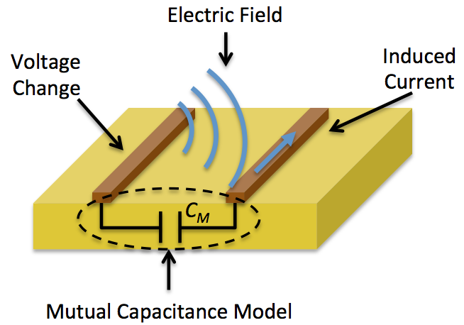
Mutual capacitance is the proportionality factor by which a current is induced in a circuit in response to a voltage change in another circuit. There is no need for these two circuits to be physically connected or even located on the same PCB for this effect to not only be present, but cause problems in your design. As depicted in the figure above, mutual capacitance can be modeled by including a parasitic capacitor between the two circuits in question. With a few basic assumptions, the induced current in a circuit can be given by the equation below.
Register for our Beginner PCB Video Tutorial Series
Perhaps this typically small coupling doesn’t seem like a big problem to you, but consider how many individual circuits you have in your design. Each one of those circuits interacts with one another through this mechanism. So the induced current in a given circuit is actually the superposition of all mutually capacitively coupled circuits acting on the circuit in question. This includes all circuits on your board and outside of it too! You can see, if care is not taken to reduce mutual capacitance, your design may exhibit undesirable behavior due to this effect.
 Did you enjoy this article?


Recent Comments